Intro
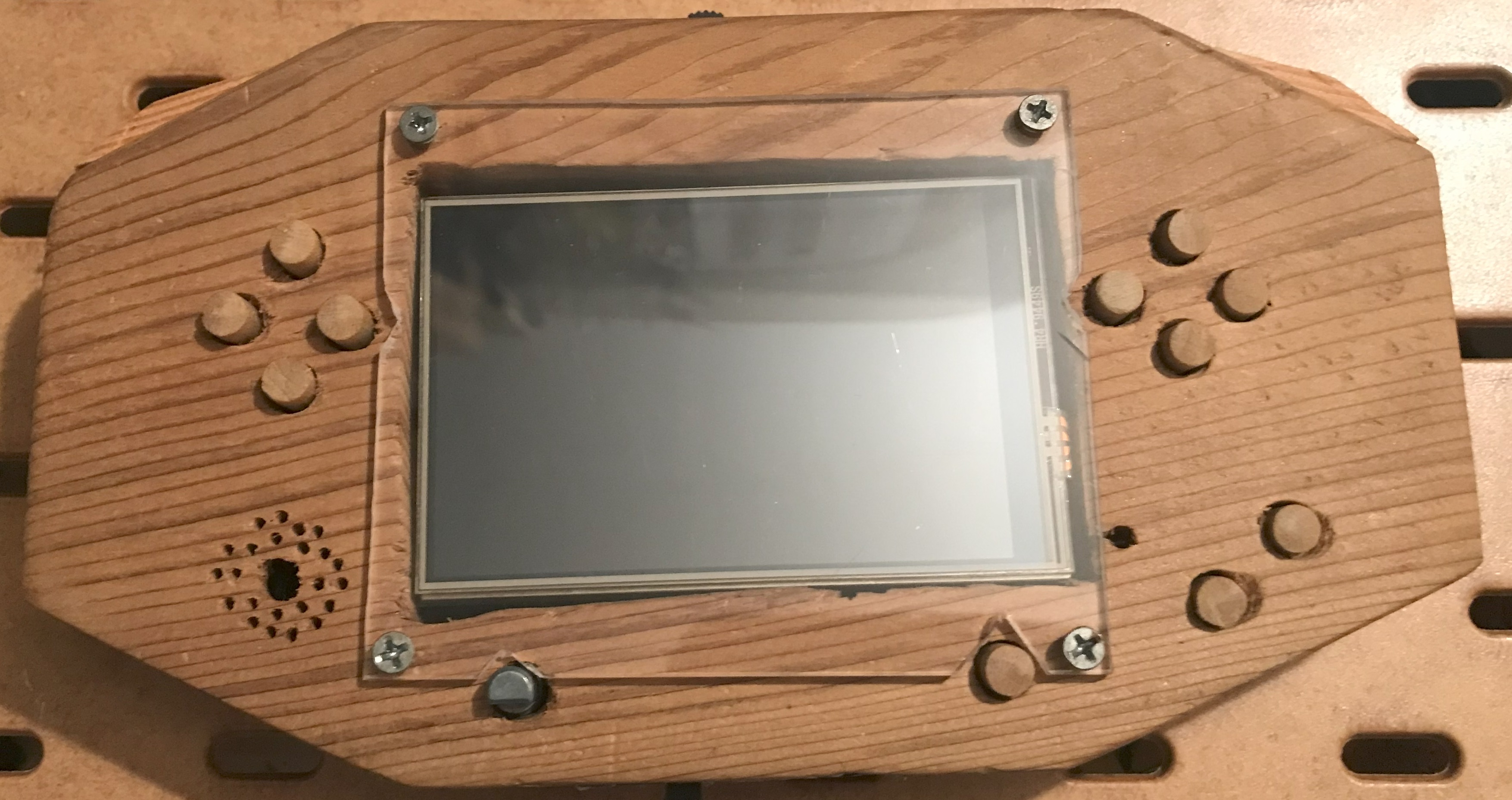
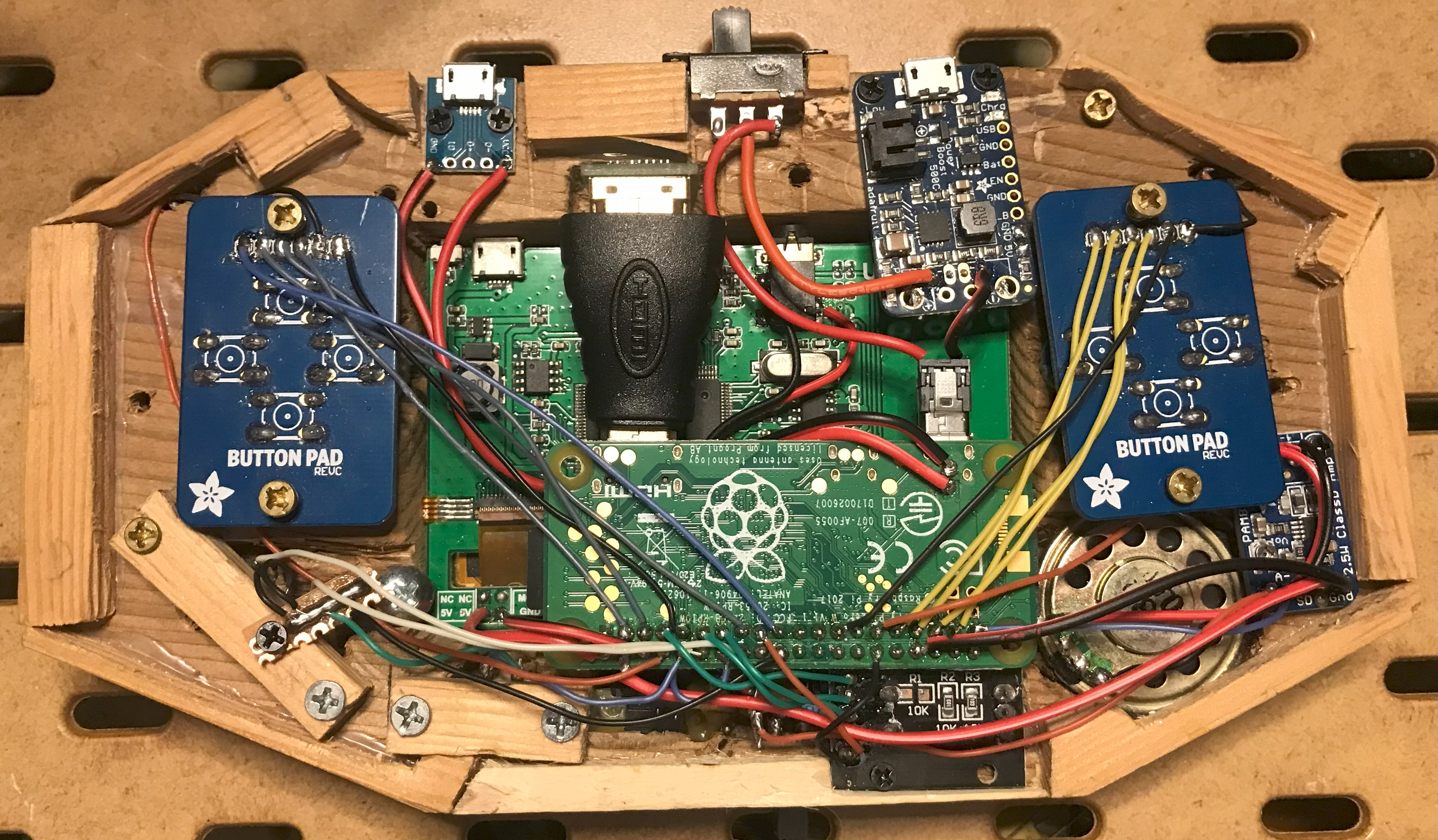
This project runs the RetroPie software with a case I made out of wood. When I first made it back in ~2019 all I had was a hacksaw and drill, so it didn’t come out perfect but I still like the look and feel of it. Recently I needed to use the RPi board inside of it for another project and when I finally got a replacement (thanks chip shortage), I decided to upgrade parts of the design and capture how it is all put together for this website. These upgrades include adding volume control, alternating power supplies, and a switch for toggling the stereo output to either the onboard speaker or an external 3.5mm jack for headphones. Since there is only one speaker in this design I also decided to convert that audio to mono after the switch, and I used a different audio amplifier to reflect that change as well. Here are a couple images of it:
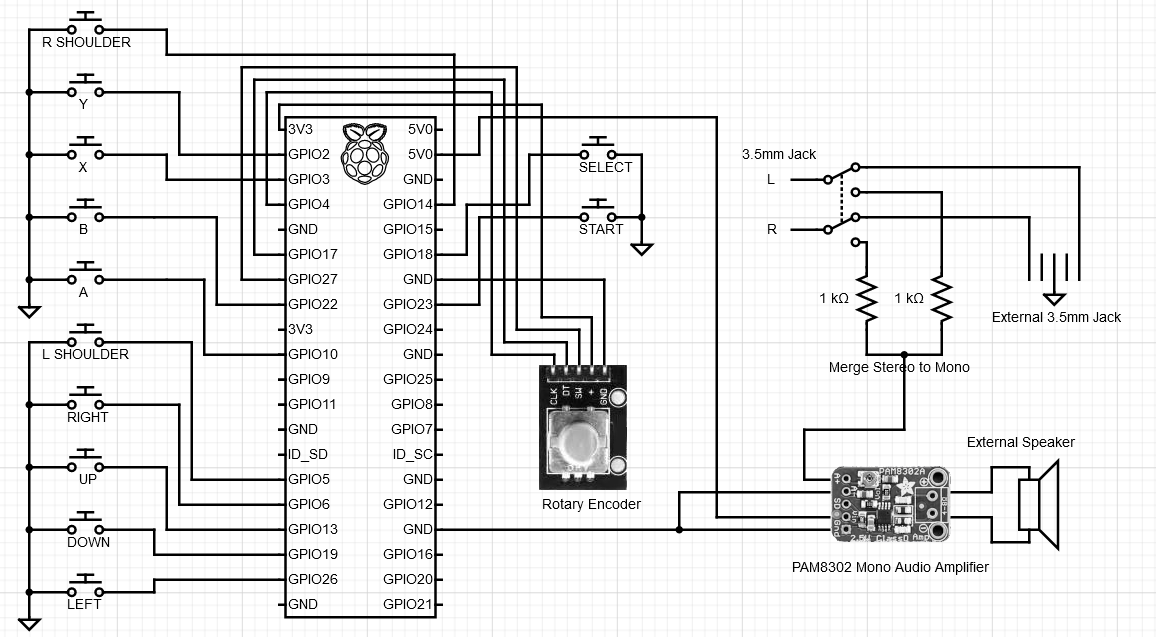
Circuit Diagram
These are the final pinouts for all the different components, outside of the power. If you see something different in the video breakdown down below, stick with what you see here - I may have changed a couple things as I was assembling it:
Hardware used
- RPi Zero W
- 3.5” LCD for RPi
- Mono 2.5W Class D Audio Amplifier - PAM8302
- 1x speaker (it’s either this one or close enough to it)
- Mini HDMI to Standard HDMI Adapter
- 1x Rotary Encoder that looks something like these
- Lithium Ion Polymer Battery - 3.7v 2500mAh
- PowerBoost 500 Charger (consider the 1000 board)
- 2x PiGrrl Zero Custom Gamepad PCB
- For the buttons I used a mix of these and these
- 3.5mm audio jack
- 2x DPDT switches as seen here (Note: one should be a 3-Position switch)
- 1x M/F Micro USB Breakout Boards like these and these
- 2x 1k resistors
- Wires, solder, soldering iron, heat shrink tubing, perfboard, wire cutters, screws, etc.
Some of the above components are very specific, however, you should still be able to find other brands or types depending on your situation. For example, DigiKey or Micro Center should have a lot of these same parts.
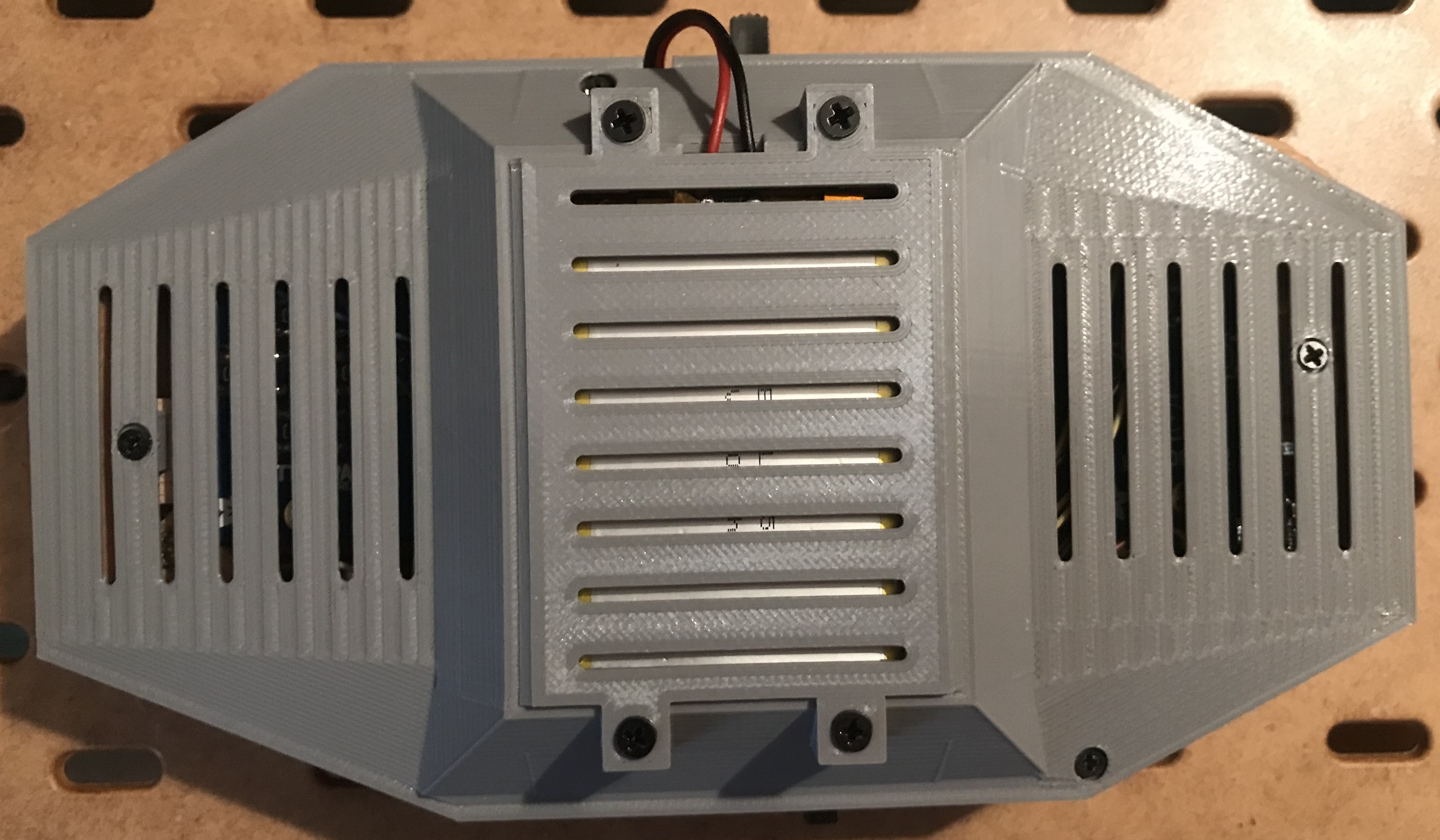
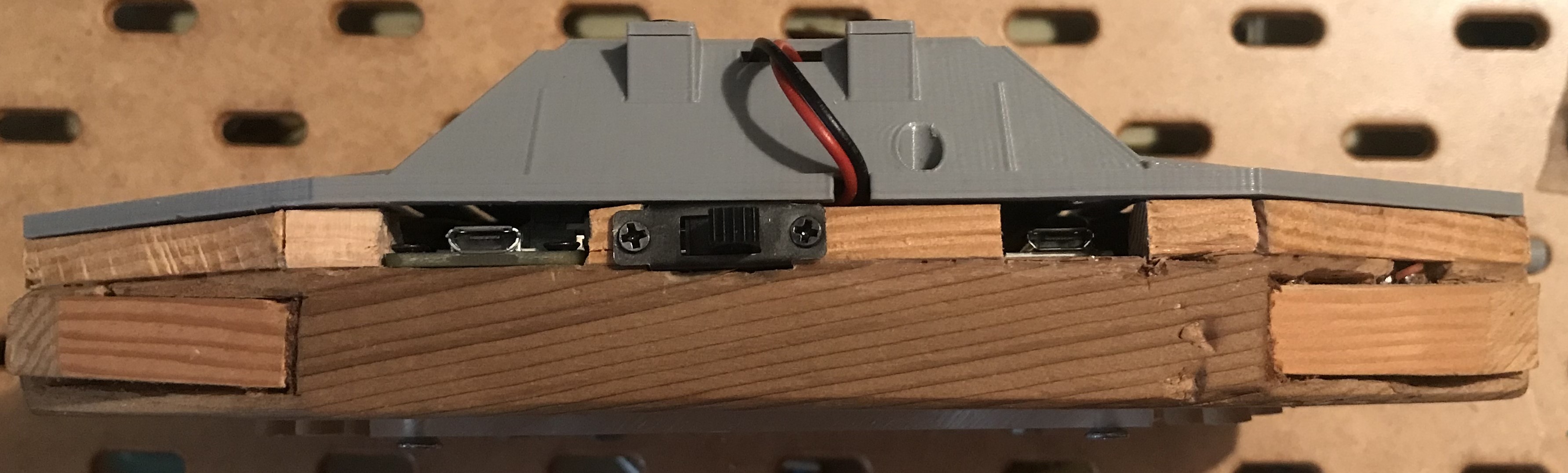
Backside
I needed to redesign the backside anyway, so I decided to do so with MatterControl and print it off. This gave me a lot more control over working with another piece of wood would have, and even though parts of the design below look strange / corrupted it prints off fine when sliced with Cura:
Video breakdown (for the hardware)
Software
If needed, you can follow along Adafruit’s guide for setting up the software side of things on their page here. I obviously deviated from their hardware setup quite a bit, ranging from the audio to the LCD to the entire casing. You will still need to set up things like the Wi-Fi and configure the buttons and they do walk you through those steps.
RetroPie
Use the RPi Imager and select the RetroPie image under Emulation. At first boot exit the startup screen with F4, then enter sudo raspi-config at the terminal. From there connect it to Wi-Fi and enable SSH under “System”.
After a reboot, ssh in and enter the following commands: curl https://raw.githubusercontent.com/adafruit/Raspberry-Pi-Installer-Scripts/master/retrogame.sh > retrogame.sh then sudo bash retrogame.sh. Select option 1, or the “PiGRRL 2 controls”, and allow it to reboot once more.
If you’ve followed my setup you will need to configure the /boot/retrogame.cfg file as follows:
LEFT      26  # Joypad left
RIGHT      6  # Joypad right
UP        13  # Joypad up
DOWN      19  # Joypad down
LEFTCTRL  10  # 'A' button
LEFTALT   22  # 'B' button
Z          3  # 'X' button
X          2  # 'Y' button
SPACE     18  # 'Select' button
ENTER     23  # 'Start' button
A          5  # Left shoulder button
S         14  # Right shoulder button
ESC       15  # Exit ROM; PiTFT Button 1
1          8  # PiTFT Button 2 (This is unused for me)
2          9  # PiTFT Button 3 (This is unused for me)
3         11  # PiTFT Button 4 (This is unused for me)
And call another reboot just to be safe.
Now configure the gamepad settings again, this time using the actual buttons after RetroPie has fully loaded.
LCD
In the event RetroPie boots up and does not fill up the entire screen (which happened to me), edit the /boot/config.txt and UNcomment this line: #disable_overscan=1. That solved my issue, hopefully it works for you as well.
Audio and Volume Control
You may need to force audio through HDMI to pull from the on-board stereo jack there, to do so enter sudo raspi-config at the terminal, and then select System>Audio and force audio to HDMI (or elsewhere depending on your setup).
To test the audio (especially the Left and Right channels for the external 3.5mm jack) use this command to alternate audio between the two: speaker-test -c2 -twav -l20. That will give you roughly one minute for testing, stop whenever with Control+C.
I finally figured out volume control with the rotary encoder. It took a while and a good amount of trial and error, but now it works and I’ve installed it to the crontab for every reboot. To download the script to your machine use: curl https://raw.githubusercontent.com/fe-moldark/wesleykent-website/gh-pages/assets/rpi/retropie/rotaryEncoder.py > rotaryEncoder.py. To install this to your crontab use crontab -e, then insert: @reboot python /home/pi/rotaryEncoder.py. This script assumes you are pulling audio from the audio jack on the LCD and that the rotary encoder is connected in the same way as the above circuit diagram. Credit to this guy for the script on getting data from the rotary encoder, I had to deviate quite a bit from how he handled the volume control but still built on what he wrote.
ROMs
There are many ways to move ROMs to the RPi, the simplest method (although a little bit slower) is the following:
- From Windows open File Explorer
- Navigate to
\\<RetroPieIPAddress>\ - Copy over your ROMs directly to the appropriate subfolders under the
romsdirectory
After the transfer, reboot the Pi and then try playing the game - this will confirm if the buttons are laid out as expected and that the volume is working.
Shutdown button
If you want to create a clean shutdown button (besides just pulling the power or flipping the switch), you can write a quick script that monitors button input and install it to the crontab. Otherwise just use the escape button to exit the current game, then press start and navigate to the ‘Shutdown’ option.
Final thoughts
This is a fun project to give a try, and there are plenty of other tutorials and designs you can follow as well. If you are looking for a more structured overview on how to put together a game console then give Adafruit a look.