The 3D modeling and slicing software
I was initially going to push this onto the main femoldark page but I figured this will be a consistently updated topic, so I might as well create a seperate space for it. I settled on designing this case using MatterControl for the following reasons:
- It’s free
- It’s a relatively straight-forward 3d design software, nothing complex like you would see with Blender, etc
- It also acts as a slicer, so I can directly export the stl files into gcode for my Ender 3 Pro
All in all, it provides exactly what I’m looking for without a steep learning curve, and I would recommend it to any beginner. The one thing that it does not allow as a slicer is the ability to edit the nozzle and bed temperature, and the print speed by layer, which I only recently needed after upgrading to a glass bed instead of the magnetic one. Since then I have been using Cura as the slicer with great results, although a bit slower (as intended).
The game console has gone through many iterations and I think I’ve finally settled on a working design. It can be difficult to tell what will or won’t work until it’s actually off the print bed and in hand, but with enough trial and error I think it’s nearing the final print stages.
There’s something genuinely fun about writing the software behind the game, assembling the hardware that will interact with the software, and then designing the case that will house the hardware. Maybe I’ll write my own linux distro just for this platform… I’m kidding, I don’t how to do that.
 Updates
(Newer updates will appear at the top here, older ones at the bottom)
Final Update
The game console is done! After replacing the BPi M5 with the RPi 4, rewiring everytihng and rewriting a good amount of the software, everything is working. You can read how to assemble and configure this yourself on this page here.
Update, June ‘23:
Not a great update. Long story short, any image BPi provides has the resolution locked into only one option it would seem. This is not a new issue apparently, and all of the troubleshooting steps and file modifications did not work. Normally something as simple as the screen resolution would not be an issue, however, my pygame window is 720x480, so being unable to set the display’s resolution to match this means I need to include the pygame.SCALED flag. This changed a normally running 30-40 fps display to somewhere around 5-10 fps. I ssh’ed in and htop revealed that, sure enough, all of the CPU cores were maxed out. Just trying to scale that window used up all of the board’s processing power.
So, now I need to replace the BPI M5 board with a RPi Model 4 (4 GB Ram), rewire everything, and purchase a micro HDMI to HDMI adapter. On the software side of things this means an entirely new image, reinstalling modules / libraries, and adopting all of my scripts to now work with either digitalio, RPi.GPIO, or gpiozero instead of the wiringpi library for BPi boards.
Update, May ‘23:
“You know, there’s probably a good reason we use circuit boards and not wires.” -Wesley Kent, May 2023, R.I.P.
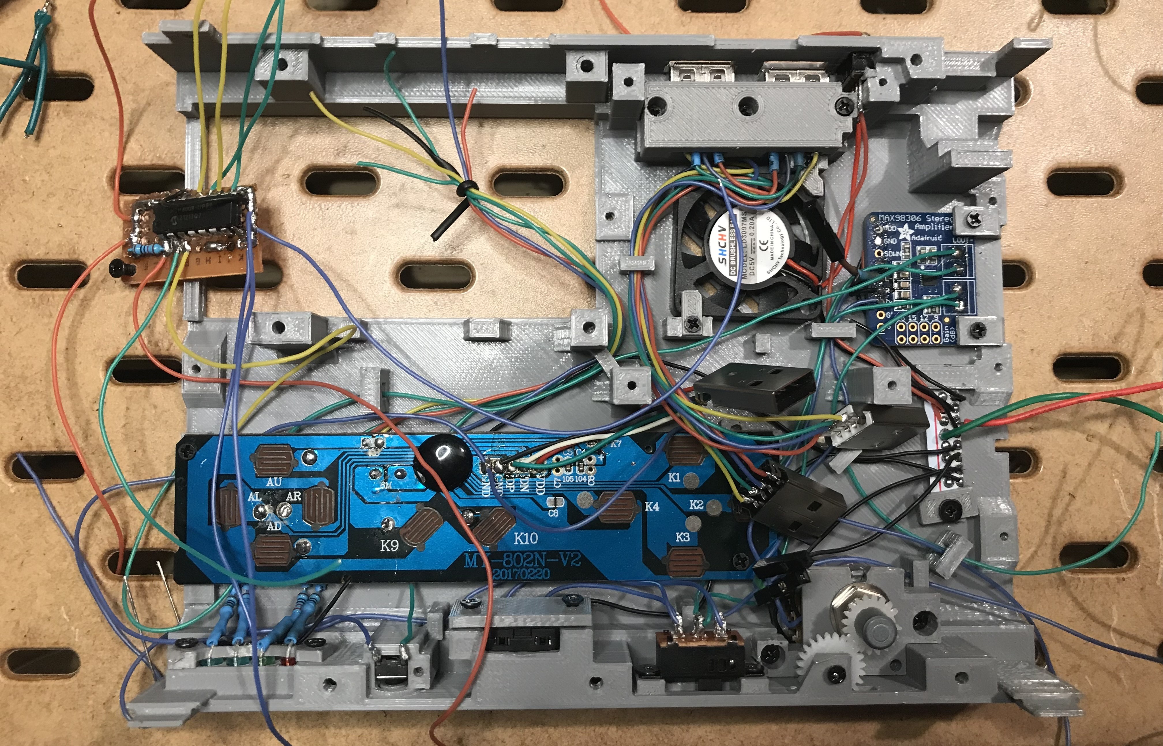
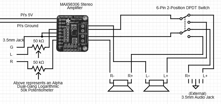
Audio has been fixed as far as the speakers go, the external audio jack is still experiencing some white noise / static. I’ll link an image of the circuit and maybe someone can see where I am going wrong. I have tried wiring that ground to the initial ground input from the audio jack, I have also tried the L- / R- output from the audio amplifier, and just a random ground from the Pi board itself. Each scenario results in that white noise, so no luck thus far, although the audio does still get through (just poor quality of course). Here is what that circuit currently looks like, and keep in mind what I’ve already tried with the different grounds:
If anyone sees my issue by all means shoot me an email and let me know. If this is in fact an issue with the ground maybe I need a need a Triple-Pole Double-Throw instead of the DPDT?? That way I could cycle the ground through there as well and keep it contained to solely the speakers or external jack. I don’t know, I’ll do some more experimentation but I don’t want to spend too much more time on it.
Something new is the analog joystick I decided to use instead of the 4-button gamepad. While this is more annoying to work with it does offer a better feel your up/down/left/right movements. Since this is an analog device I did need to purchase the MCP3008 to convert it to a digital signal that the Pi board can work with. Surprisingly, Adafruit’s site was one of the cheaper places to purchase that converter from. I’ll show the wiring for it down the road. The front side panels are now both complete, reference the videos below for more on that.
Update, January ‘23:
The backside is complete as far as the 3d-model goes, all that’s left is to begin to wire everything together and make sure it all works as expected.
I am also working on a new design for the front side pieces that will allow for a neat way to disassemble the game console when needed, but that will take some time still. The current plan on that front is to cut up some unused 2x20 M/F GPIO headers for the Raspberry Pi to create connectors that will be entirely removable without needing to solder / unsolder things. It will make more sense once I’ve actually created the model and printed it off - for now, the update is below:
*Note: Part 2 of this is me explaining a fix for what I thought would work for the audio in the last few minutes of Part 1 but did not play out as expected. Sound is now working, and I also decided to include a DPDT switch and a spare audio jack for multiple forms of outputting audio besides just the speakers.
Update, December ‘22:
Back side pieces are nearly complete, just need to perfect the track and better secure the piece holding the spring to the main board. I’m hoping to start doing some final prints in the near future so I can begin wiring everything together and actually test it out.
Update, November ‘22:
The side pieces are now both complete and the center pieces (front and back) both nearly finalized. Every piece so far has taken at least one test print to identify some very minor adjustments (usually just a millimeters or so), after that everything prints off as expected. The downside is the time it takes to print - the side piece you see in the first video below took 5 hrs to print, so it’s never a “quick” fix. I’m also paranoid that the 3D printer will catch on fire, so I never run it while I’m away. Check out the two updates below:
Update, October ‘22:
One issue I am working through right now is redesigning how the battery is going to work, which actually has more layers to it than you might think. What I’ve currently settled on should work, however based on some measurements it likely means I will have to heavily redesign the backside as the RPi board and the Battery case may end up switching places and rotating. The issues only compounded once I realized that some of the specific components I had bought (like the hdmi ribbon cable) were tailored to a very specific length, and now that everything is shifting I’ve got to reorder a longer one. Not the end of the world, but something that will set me back time-wise. Check out the update below: