Introduction
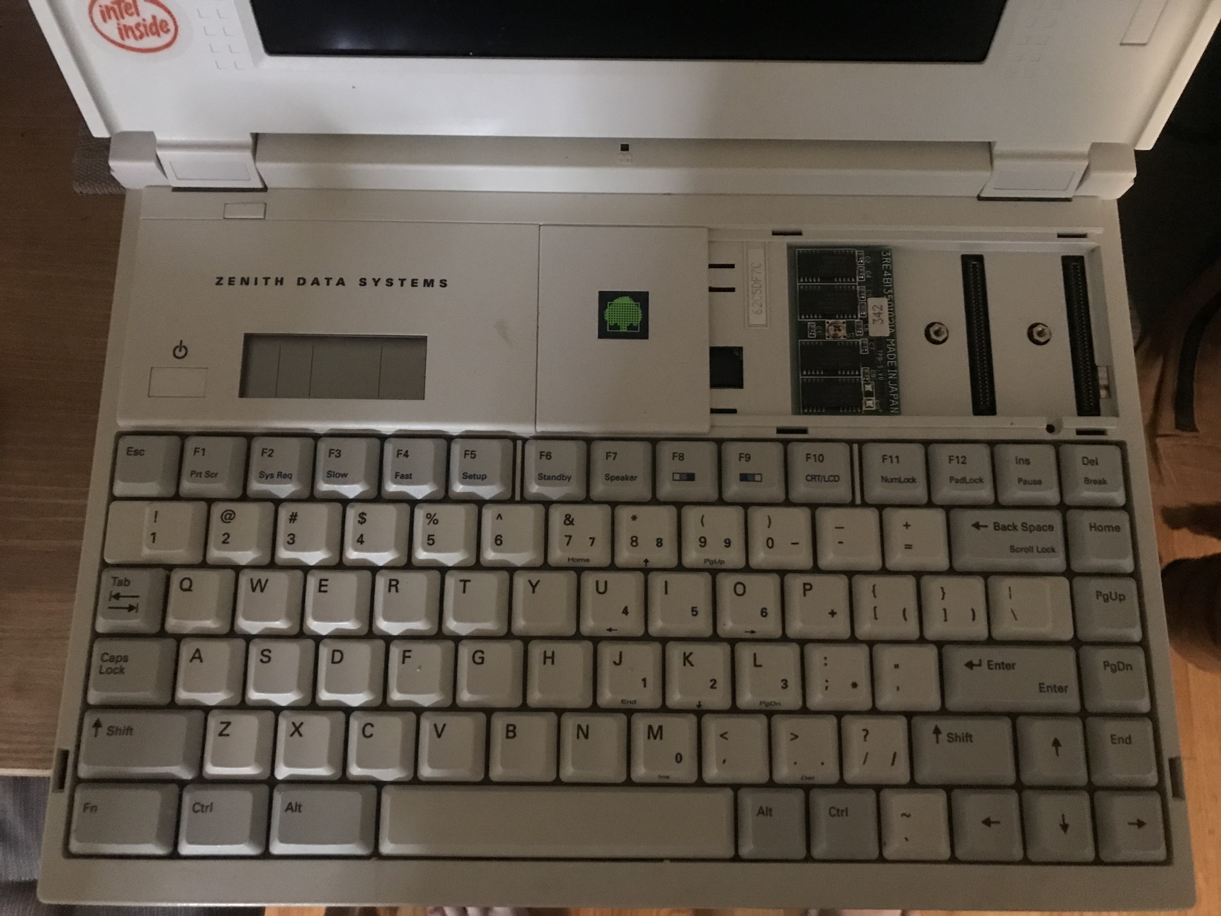
I’m modernizing a non-functioning Zenith Data Systems laptop that was made in the 90s using a Raspberry Pi 5 - well, I’m on backorder right now, so it’ll take a few months. Here is the laptop / keyboard:
Naturally I wanted to use the original keyboard from the laptop but since we are talking about a very old (and proprietary) keyboard there is no easy plug-and-play solution. Having worked on some keyboard injectors in the past I know you can emulate a keyboard over USB with a microcontroller, so somehow I need to configure the device to interpret inputs from the two FPC cables and then send that data back out as keystrokes. Thankfully, this guy has already made an entire step-by-step process to decode a keyboard’s matrix.
Hardware
- 1x PJRC Teensy 4.0
- The keyboard itself (model: Zenith Data Systems Z-note 433Lnp+)
- Some kind of FPC breakout board connector - I cut the original connectors out of the motherboard (RIP)
- 30 gauge wire, solder, soldering iron, etc.
Configuring this / the software side of things
I’m not going to break this down step by step since it would just be me copying the guy I linked above, but explained worse. Instead I’ll give a broad overview of what you are doing and explain some things that had me a bit confused going into this project.
After wiring every pin from the FPC cables to an I/O pin on the Teensy you need to compile and upload the Matrix_Decoder script (again, reference above). Once it is running, you use a separate text file that has every single key that could exist on the keyboard, and line by line manually press every key as they appear on the list. Each key press will produce two numbers for the FPC Pin numbers (NOT the Teensy I/O pins). Using these numbers you will create a matrix (or array) of these numbers that will look something like what I generated below (csv version here):
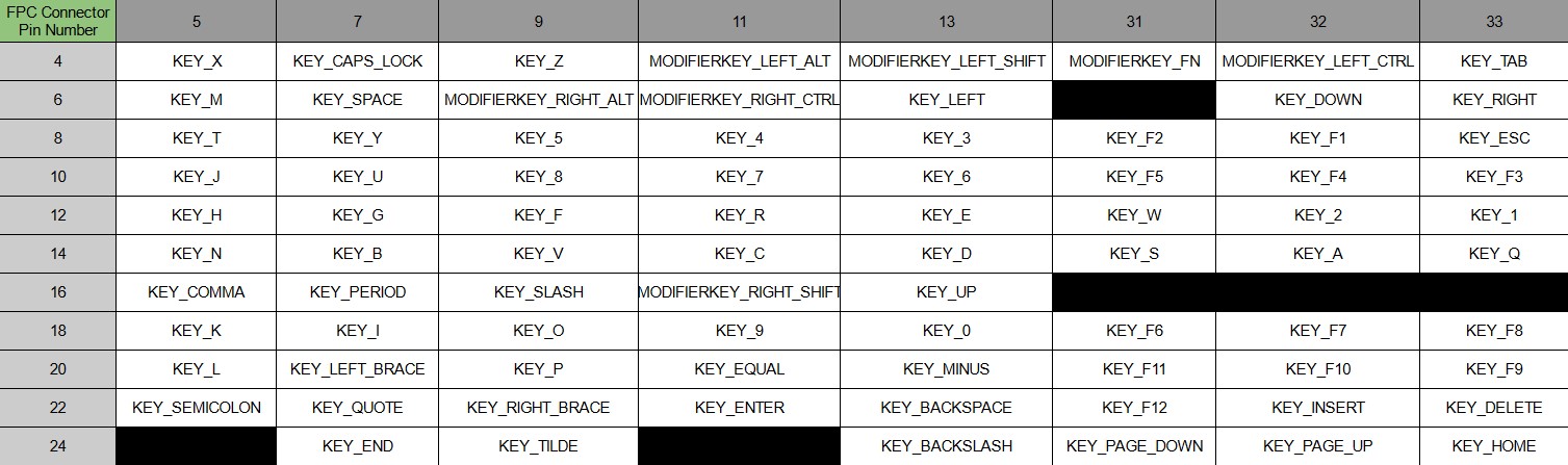
Now, how do you determine which numbers are the rows or columns / outputs or inputs? Well, from what I read there are typically 8 input columns and looking at the ribbon cables from the keyboard I noticed one had 8 pins and the other had 11. I went with my gut and sure enough, that was the correct guess. An interesting way to look at this is to actually reference the connections inside the keyboard itself. I took the keyboard apart and snapped this photo:
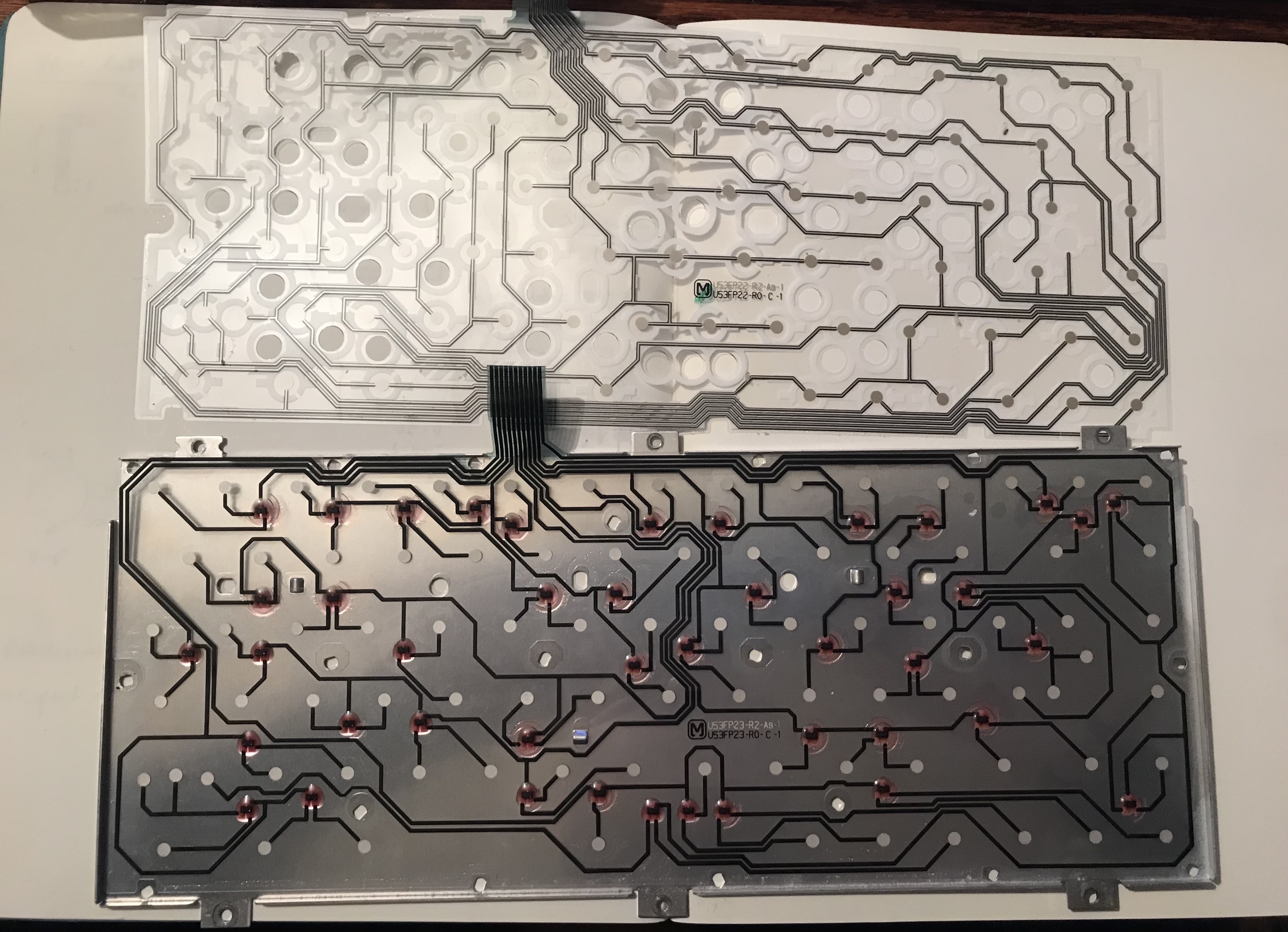
Looking at this gives you a bit of a headache because it is not set up in direct columns and rows like you saw in the matrix above. Another way to look at this is to manually trace each of these which gave me something that looks like the below picture. Each color represents keys that are linked across a single contact of the FPC cable and keep in mind this was only for one of the overlays.
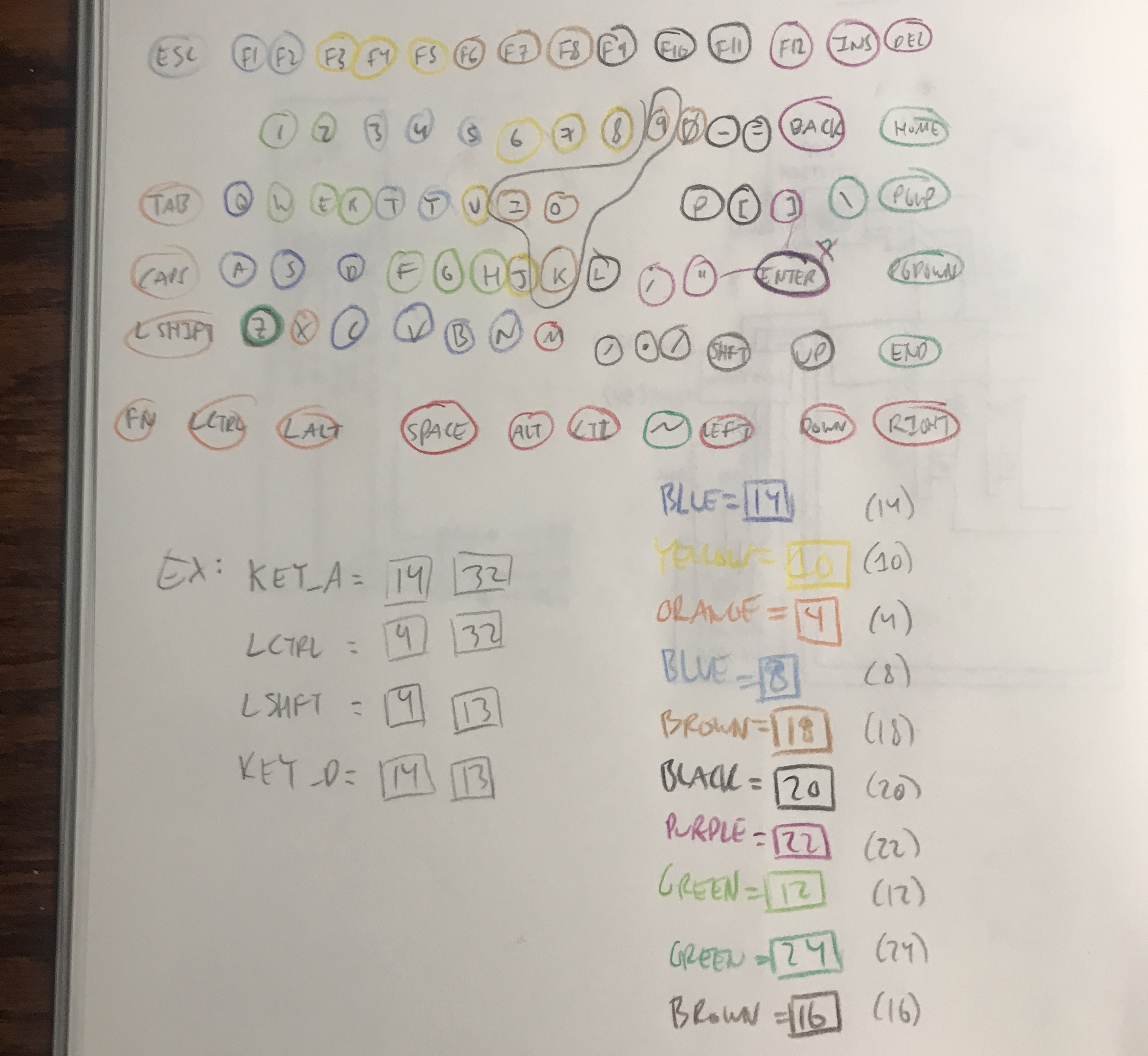
Visually this helps you confirm the numbers that you got from the first text file after running that script and manually pressing each key. Looking at what keys are in the same ‘group’ reveals the common numbers between them. This step is not necessary, but it is fun to take the keyboard apart and manually trace the wiring. It also helps you identify issues with the keyboard, for instance if 3 or 4 keys are not working that might point to a break in the wiring somewhere that would otherwise not be obvious. Once you have this matrix you move onto the next step which is translating the FPC numbers to their Teensy I/O pin numbers using a table that guy already provides. From there you will need to customize the keyboard ino script with how your own matrix looks like, and this applies to the “normal” keys array, the “media” one, and the “modifier” one. Again, I wont be explaining this in depth because it has already been done in depth on his page here.
In the end you are able to directly plug in the keyboard to your device over USB and use it to its fullest extent. You can use regular keys like letters and numbers, modifier keys allow you to use common shortcuts like CTRL-C or SHIFT+letter for capital letters, and function keys like Fn+F1 for things like Print Screen. You can even program specific keys to perform different functions than they normally would - it’s all up to you. All of that in the brief video below:
zenith_keyboard_with_teensy from Wesley Kent on Vimeo.
Nimble NBK-2104-5/S DIN 5 Keyboard
I also did this for an old Goodwill-find keyboard, complete with a usb-c breakout board and cable. Reference this folder for the key mappings.
Conclusion
Well, another part of this laptop modernization project is done. Next will be the audio which should be fairly straight forward - the LCD module has L +/- and R +/- output, so that will be going through a 3P3T switch. That throws your 3 channels L+, R+ and combined grounds to three options - mute (goes nowhere), a speaker, or an audio jack. If that is as simple as I expect the next step will be using a cheap microcontroller that will measure the voltage coming off the battery to estimate remaining battery capacity and use Adafruit’s 4-Digit 7-Segment FeatherWing to display that as a percentage for the user. If you look at the first image on this page, it will be replacing the old LCD there on the top left next to the power button. And that’s all for now. Thanks for reading this far.