Introduction
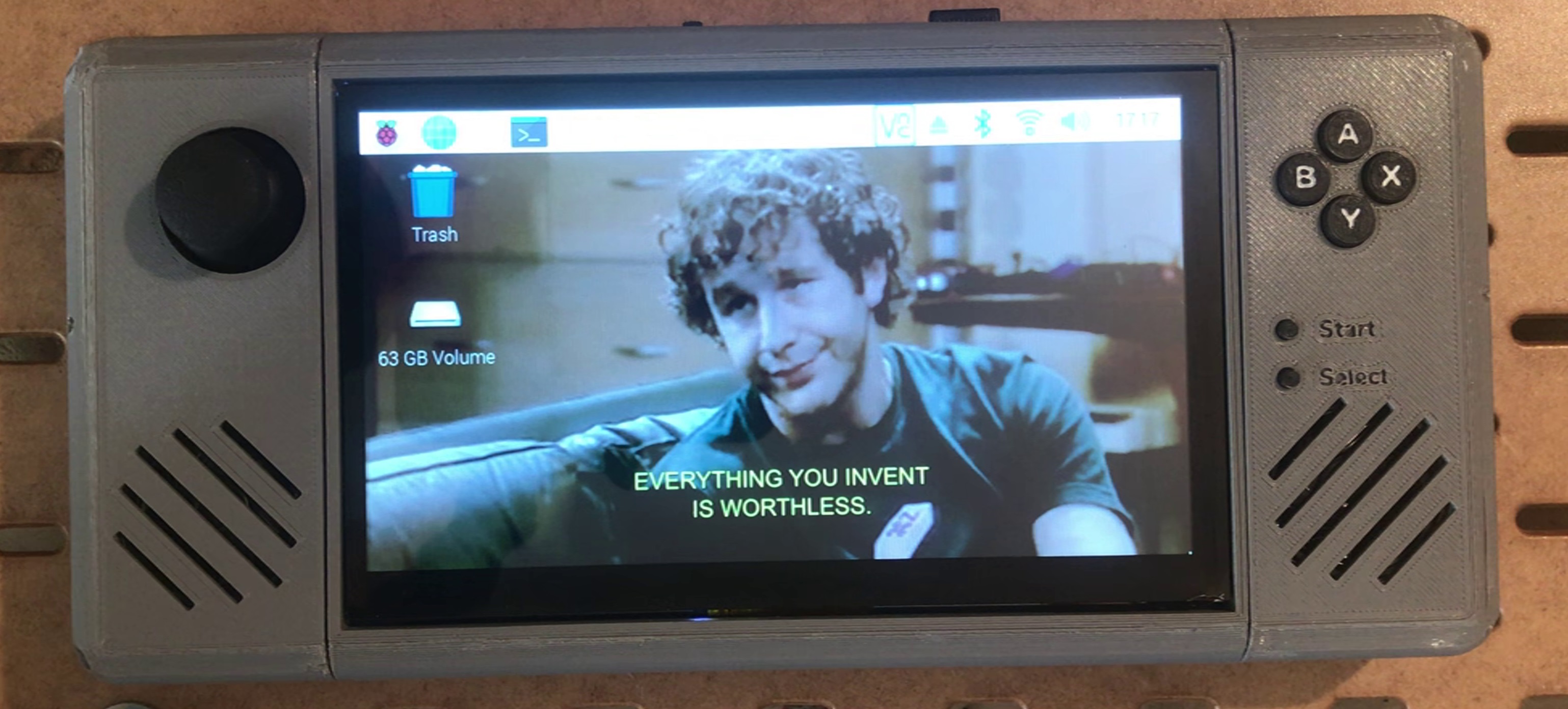
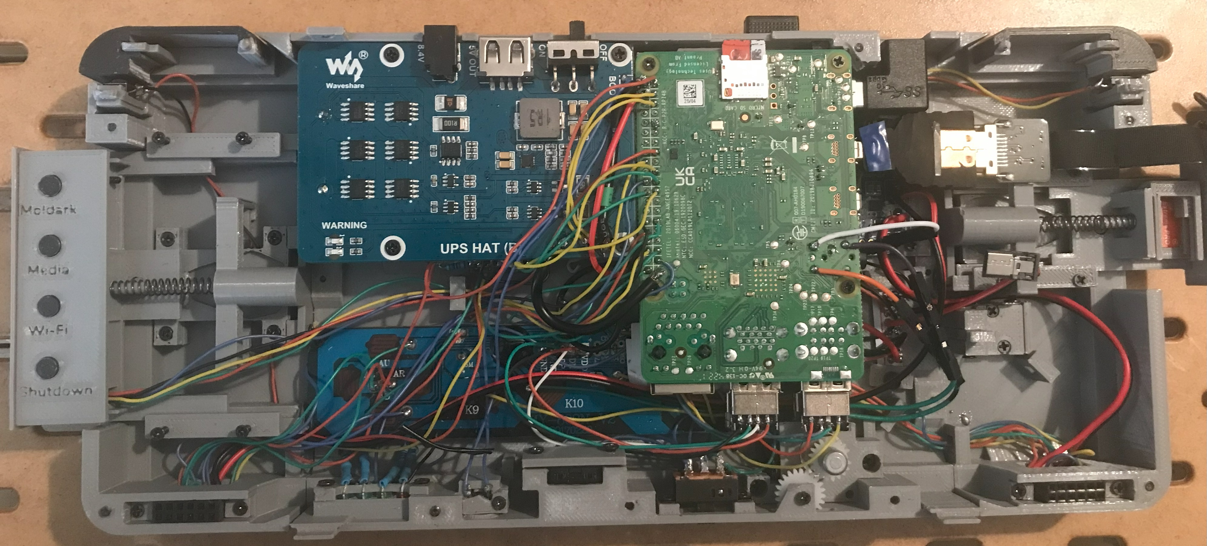
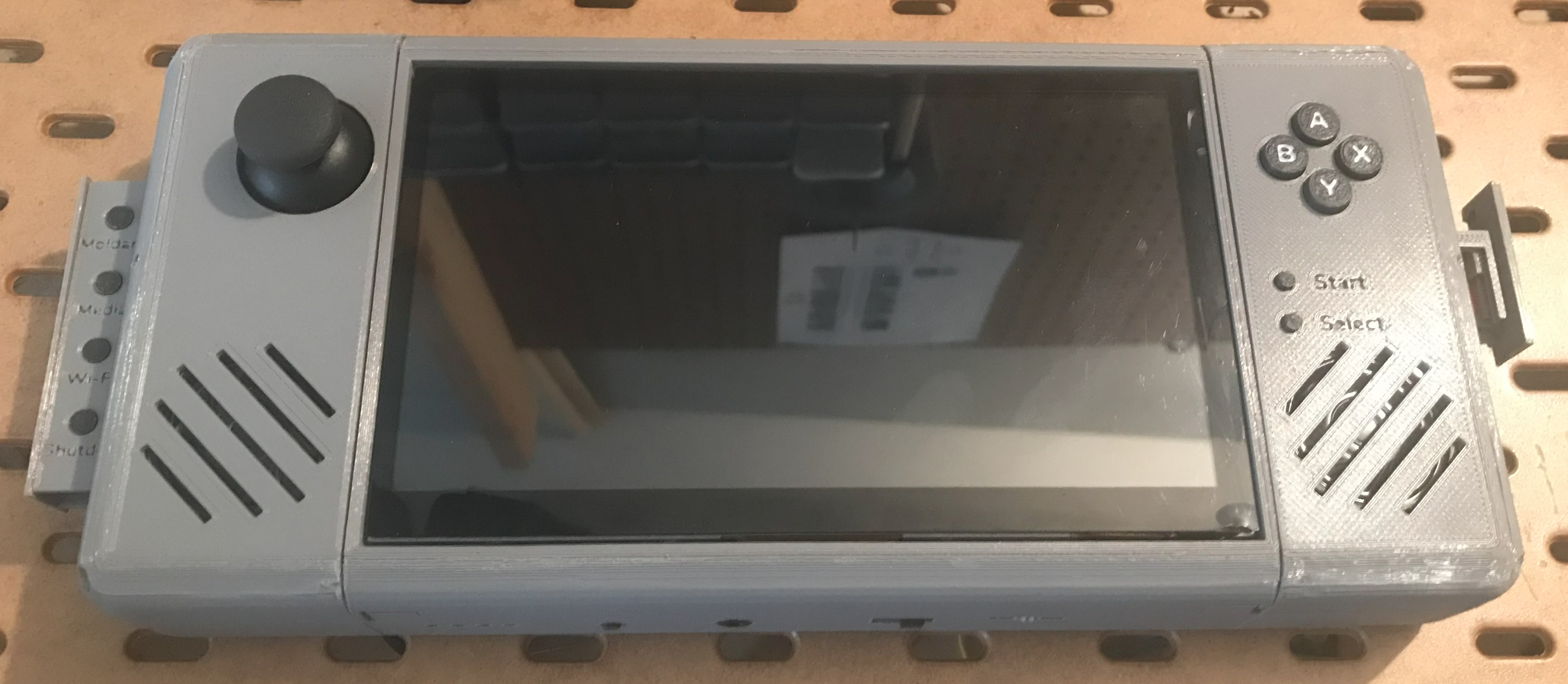
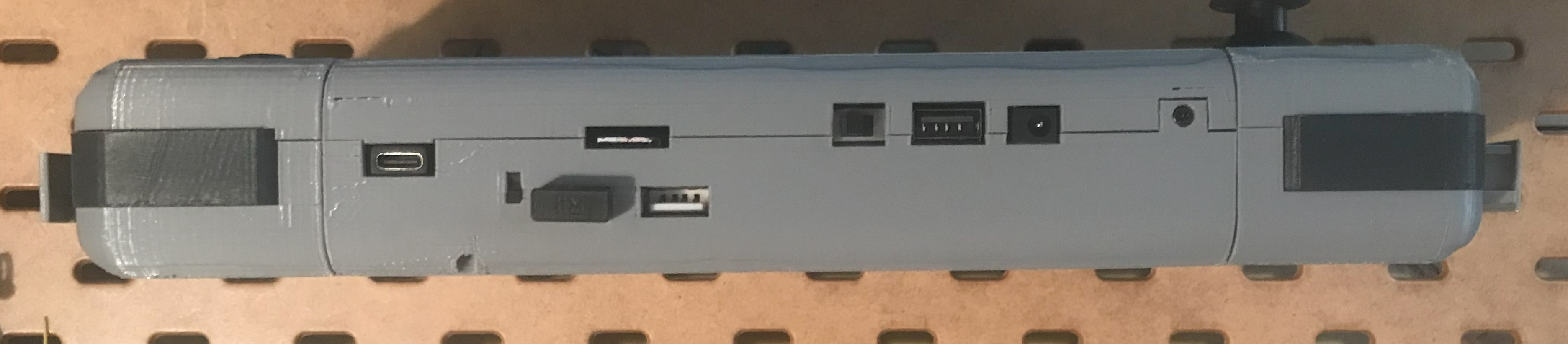
To begin, these notes are as much for myself if I ever need to set this up again or troubleshoot issues as it is for someone reading this for the first time. There are a lot of moving parts to this and it is easy to get lost and wire things up incorrectly. This device represents far too many hours spent in designing and assembling a game console I will be using for a game I have been writing since ~2016. To give you an idea of the amount of time and effort that went into this there are 71 individual pieces that needed to be designed and printed off, 112 wires cut to correct size and connected, and 105 screws used to secure everything in place. On top of that you have over 65 electronic components ranging from simple things like buttons and perf boards to analog-to-digital converters, the UPS device, the audio amplifier, and so much more. I did manually count them so give it an error margin of +/- a few. All of this to say there is a significant time commitment needed if you want to set this up yourself. Here are some pictures of the final product:
Video breakdown
I have a feeling the following wall of text might scare some people off, so here is a video breakdown of everything you are going to hear about which showcases the various features of the game console.
The Hardware side of things
Before jumping into the software side of this project, here is a list of all the hardware components you will need (or at least something similar enough to what is seen below):
Parts / Boards needed
*Goes without saying but none of this is sponsored, this is just where I happened to source the parts for this project from. If you can find these pieces cheaper elsewhere, go for it.
- 1x Raspberry Pi 4 Model B (4 GB Ram)
- 1x Waveshare UPS HAT (B) and 2x 18650 batteries
- 1x 7” LCD
- 1x Stereo 3.7W Class D Audio Amplifier - MAX98306
- 1x Alpha Dual-Gang 16mm Right-angle PC Mount - 5K Audio
- 4x 220 Ohm and 1x 10K Ohm Resistors
- 4x Diffused 3mm LEDs
- 1x Analog 2-axis joystick (This one should work, I got mine from a sensor module kit 4+ years ago)
- 1x MCP3008 Analog-to-Digital converter
- 2x PiGrrl Zero Custom Gamepad PCB
- A mixture of these, these and these buttons depending on purpose and preference (overall 13 buttons are needed)
- 3x speakers (yes, three)
- 1x 3.5mm audio jack breakout board
- 1x Female GPIO Header and 1x Male GPIO Header
- 3x Male and 3x Female USB Type A breakouts like the ones seen in this kit
- 1x SPST or SPDT switch
- 1x Fan
- 2x A1 Ribbon FPV Connector and 1x FFC Ribbon Cable 5cm
- 1x 3-Pos 6 pin DPDT switch that looks something like this
- 1x USB joystick (this one should work, I got mine in 2018 so it’s no longer available), and you’ll need to rip the guts out of this thing
- 1x 90 degree USB-C right angle adapter (option 5)
- Wire ranging from 30 AWG for the buttons / LEDs, to 22 AWG for the speakers and some common power lines, to 16 gauge wire for the 5V 3A lines between the UPS and Pi board
- Solder, soldering iron, heat shrink tubing, perfboards / breadboards, wire cutters, etc.
- 2x plastic gears, 3x springs and superglue (reference video for more on this)
Many of the above components are very specific, however, you should still be able to find other brands if something is out of stock or the link no longer works. For instance, DigiKey or Micro Center should have a lot of these same parts.
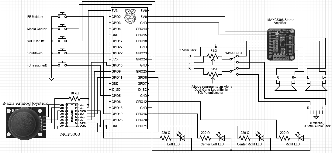
Circuit diagram
This is the final circuit diagram for the game console. Note it does not include wiring for the USB extenders or for the joystick buttons, however, those simply connect directly to their respective boards. The other two things that require some wiring not detailed below are for the fan and power to the LCD screen.
3D-prints
As stated in the beginning, there are 71 different parts that need to be printed off for this project. I’ve broken all of these down by their section and each file can be sliced using Cura and printed off a print bed of at least 220mmx220mm, which for me was the Ender 3 Pro. I will put the link to the directory housing the final STLs to print off here. Note that many of the subdirectories have files named something similar to modified_x - this means some file in that folder has been modified and to use that in place of the original. I’m too lazy to go through, correct and reupload every minor change which is often only a millimeter difference, and sometimes even less than that. You can also view the files on my Sketchfab account here, but those only have the final STL prints and none of the modified MCX files on Github.
Assembly
For instructions on how to assemble all of this you have two options. The first (and less than ideal method) is to simply look at the circuit diagram and the final pictures of the game console to assemble this and wire it up. The other option is to use the videos I have made about assembling everything on my YouTube channel here. The only downside is that those videos were of me actively creating the game console, so some of the wiring and hardware components have changed. Your best bet is to use both and find the middle ground between slightly outdated assembly videos and an up-to-date circuit diagram. If you have any questions feel free to reach out.
The Software side of things
Configuring the basics
Let’s start at the very beginning with the OS. Download the RPi Imager tool and use the most up-to-date Raspbian Desktop version and flash the sd card.
After the initial install and boot run the typical sudo apt-get update and sudo apt-get upgrade - this will take some time. From the raspi-config settings enable the following interfaces: SSH, VNC, SPI, I2C. While still in the raspi-config settings go to “Advanced” and choose the expand filesystem option. Assign a static IP address for the system or assign one to it from your router based on the MAC address and then go through the setup process for VNC.
Set the resolution to 720x400 using preferences > screen configuration. Alternatively, you can use the /boot/config.txt file to manually assign this using whatever hdmi_group and hdmi_mode that resolution falls under. Lastly, depending on your screen you may need to uncomment the disable_overscan=1 line in order to use the entire screen and remove any black borders. Under raspi-config force audio through the 3.5mm on-board jack. If you choose to connect the stereo channels from the LCD you will need to force that audio output to the HDMI option instead.
Modules / libraries to install
Install all of the below libraries/modules for both the pi user AND the root user (switch with sudo su):
pip3 install python-vlc
pip3 install spidev
sudo apt-get install python3-pygame
That last step will install Pygame 1.9.6 NOT 2.4.0. THIS IS IMPORTANT - 2.4.0 does weird stretching for the screen while 1.9.6 does not do this and simply does a pixel for pixel thing with surrounding black borders (if applicable, which for my situation it is). Do not try to install pygame over pip!
Downloading my scripts for monitoring, a media player, and testing the joysticks
I’ve already written these scripts and they are available here. There are some other files in that directory that are used within the script including audio and image files.
Regardless of the filenames in the directory they must be locally saved as monitorAndControlv3.py, showcasev3.py, and mediaCenterv3.py (respectively). You will need to set the permissions for those files to 750 or just make them executable with a quick chmod +x filename.
You may also want to modify the scripts to not perform some of the steps I do. Here at home I have a local file server that I am using to update new versions of my game by mounting a shared folder to the RPi and pulling the most recent file. I still need to run the monitorAndControl script through some error handling checks, so you might be the guinea pig if you set this up yourself.
Configuring the 2-axis joystick
I won’t copy and paste this - just follow the steps listed on the webpage here. You can use their script or one of mine to confirm if the joystick is working. In either scenario if something is not working ensure SPI has been enabled from raspi-config, you have rebooted after enabling it, and that everything is hooked up correctly from a hardware perspective. Note: the power input used for this device is better with 3.3V and not the 5V, although both should work.
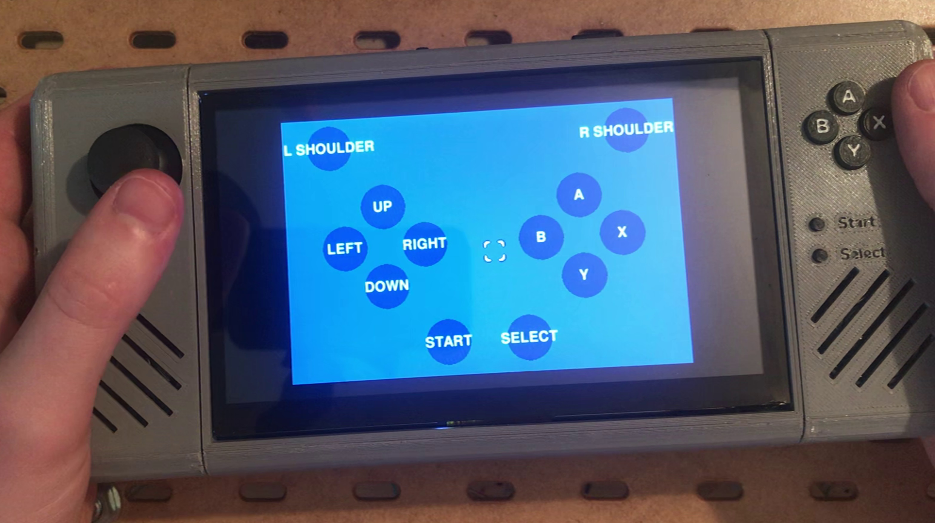
Installing an example Pygame program to test the buttons and LEDs functionality
To download the script I wrote execute the following command: curl https://raw.githubusercontent.com/fe-moldark/wesleykent-website/gh-pages/assets/GameConsole/finalShowCasev6.py > showcasev3.py (the source filename might change as I update it). Pygame should already be installed, so go ahead and try running it with sudo python /home/pi/showcasev3.py. If this throws out an error about missing the pygame module try running it with python3 / python3.x instead. Also in the event you get some errors regarding missing modules called libsdl-ttf2.0-0, run a quick sudo apt-get install python3-sdl2.
This script will ensure everything is hooked up correctly and the button inputs are interpreted correctly. If not you can adjust the script as needed. You can also test if the audio is working by pressing down on the joystick (it has a button there and this will play some audio you should have downloaded from the GitHub link earlier).
Script for monitoring button status and the LEDs
Perform the same steps just mentioned but for the monitorAndControl script and ensure it is executable. Install it to the crontab using crontab -e, then append @reboot sudo python /home/pi/monitorAndControlv3.py at the bottom.
The four buttons on the panel are configured to execute the following from top to bottom:
- Start / stop the game I am writing (for this example we will use the
showcasev3.pyscript) - Start / stop the media center (covered later)
- Toggle the Wi-Fi interface on and off - saves a bit of resources and power when not needed
-
Perform a clean shutdown of the system with a
os.system('sudo shutdown -h now') - The fifth button at the bottom has been repurposed from battery monitoring to act as the UPS’ “reset” button. For whatever reason whenever batteries are removed and reinserted this on-board button needs to be pressed to get the UPS working again. I simply unsoldered the button it came with and wired it up to the button down below after the battery monitoring broke. I will talk about that next.
Link to the entire script can be found here. I won’t go over it in detail since it is only a couple hundred lines long and relatively easy to follow. Every button on the pop out panel has some sort of LED sequence to indicate what is happening. The first two buttons will have either a three-blink sequence of the red or green LED depending on whether or not it is killing or starting the process. The Wi-Fi toggle button will either blink red three times when turning the Wi-Fi off, or alternate flashing between the two blue LEDs until a) Wi-Fi is connected and connections are making it past the LAN to one of Google’s DNS servers and then the green LED blinks three times or b) after ~15 seconds of trying to reach out to their servers it will simply stop and blink the red LED three times to indicate that failure.
NOTE: There was some extensive and infuriating troubleshooting that needed to happen here. This script (as seen in the crontab) must be run with escalated permissions, however, any process it calls afterward also executes it as sudo. Since I could not find a way to execute the initial script as one user and then another script as a different user within that first script, you may need to switch users with sudo su and then install the same modules for them.
Configuring battery monitoring
Fair warning: This was working and suddenly stopped. I don’t know if it was a hardware failure or if something I did broke this (both from the software or hardware side of things), so go ahead at your own risk.
The UPS should already be connected to the Pi board over the I2C data and clock pins - look at how it would be connected if it was using the “pogo pins” it came with. Before adjusting the script you should already have I2C enabled in the raspi-config settings. Now at the command line execute gpio i2cdetect and check if any devices are showing up there. If not, try a reboot, check the physical wires, ensure the UPS is actually turned on, and ensure dtparam=12c_arm=on is NOT commented in the /boot/config.txt file. Once that command detects the device we can move on to the script.
Waveshare provides a script that monitors the battery status and the steps with which to do so are located here. We will follow the initial installation steps and then I will show you the steps I went through to get it working for me. Go ahead and execute the following commands:
sudo apt-get install p7zip
wget https://www.waveshare.com/w/upload/4/4a/UPS_HAT_B.7z
7zr x UPS_HAT_B.7z -r -o./
cd UPS_HAT_B
python3 INA219.py
Unless you are lucky this script will not work out of the box and you will need to change a few things:
- Install the new version of smbus with
pip install smbus2. From what I’ve read the old version only works with Python 3.5.x and as of right now new installations of Linux come with 3.9.x. - Discover which file that I2C device is associated with using
ls -la /dev/ | grep i2c. In my case, this resulted in onlyi2c-0, NOTi2c-1. - Modify the
INA219.pyscript you downloaded with the following:- Replace the
import smbustoimport smbus2 as smbus. This will use the newer version of smbus but not require any further modification of the script. - Locate where the
INA219class is defined. That class auto assigns itself some parameters includingi2c_bus=1. Depending on what step 2 told you (again, for me it showed be the only device there wasi2c-0), modify that parameter to bei2c_bus=xreplacing thatxwith whatever you discovered.
- Replace the
After that try to run the script once more. You should get some text printed out about every second showing information like the charge / discharge rate, remaining battery as a percentage, etc.
Now that you have confirmed the battery monitoring script is working we can modify what it returns to use in our script for the crontab. What I decided on was only returning the battery percentage and only executing this one time, i.e. one time whenever a particular button is pushed instead of a never-ending battery monitoring script that consumes resources. We will edit this with the following:
- Remove the
whileloop so this only executes once and change the output so only prints the out the battery percentage left - Once confirmed working we can return this value to the primary script and convert the percentage into something the LEDs can show, e.g. blink patterns, which LED colors light up, etc.
If you can get this working then I would change the fifth button to work as a battery monitor and keep the on-board UPS reset button where it’s at. Once I had this working and I was all happy I shut down the device for the night and the next morning it would not work. I do not know where the issue is as I have tried this on both a BPi M5 and a RPi 4, fresh SD cards with a brand new OS, and resoldering both wires.
Mounting local NAS
Create a credentials file for accessing the shared drive named something like credentials and give it just two lines:
username=pi
password=sorryStillNotDumbEnoughToGiveOutMyPasswords
Keep in mind that these credentials are stored in clear text, so adjust the permissions accordingly.
After some trial and error the following command works with the crontab: @reboot /bin/sleep 45 ; sudo mount -t cifs //192.168.11.19/MyMedia/sharedWithPi /home/pi/sharedWithPi -o credentials=/home/pi/credentials. Note that parts of the monitorAndControlv3.py script involve the shared drive, so either allow some time for the mount process, add some kind of sleep or wait function, etc. Or, I don’t know just don’t press any buttons the second the game console boots up.
Media Center
I programmed a simple interface so the user can navigate between directories and play video files. My setup has a 64GB external USB drive, so that is where I will be storing my movies, tv shows, and more that I have ripped for almost the past 10 years.
This program starts when the second button from the top is pressed, and uses the on-board controls to navigate, select files to play, toggle fullscreen, etc. The buttons have been configured as the following:
- (A) is select
- (B) is deselect
- (START) is play / pause
- (SELECT) toggles fullscreen
- (UP / DOWN) is for navigating
- Volume control is achieved through the manual potentiometer on board the game console. Default volume for VLC is always set to 100% so you still have full the range
Note on installing RetroPie to a separate sd card
Initially I wanted to install RetroPie to run as an application on the main OS by clicking a button, however, the install fails due to an incompatible omxplayer package when on the RPi 4. A work around for this is the pre-built RetroPie image (not as an application / software). In a way this was actually a good thing since I am intentionally lowering the resolution quite drastically for my game and hosting RetroPie on a separate OS means I can scale that resolution back up. There are abundant tutorials on how to install the RetroPie image, so I won’t try and throw my hat in the ring. YouTube and the internet can guide you. I do have the spare sd card with that image on board the game console - the pop out panel on the right holds it as well as a tool to extract the sd card from the top.
Note for myself: DS emulators must be manually installed –> use the DraStic emulator and lower the resolution by just a bit to run at full fps. Also note the traditional escape combination used with other emulators will not work - go to the settings using the “m” key (using a keyboard), and assign those keys (up/down/left/right and select) that way.
BananaPi M5 Notes ONLY
As mentioned in a previous update, I needed to shift away from the BPi M5 for some annoying reasons regarding the resolution and the processing power it takes to scale a pygame window. If you want to stick with this board for other uses, however, here are some notes I made as I was writing the scripts and configuring the system:
- Get the image from the Banana Pi M5 Wiki page
- You will need a USB Wi-Fi dongle as there is no native wireless card, unlike the RPi 4. I would recommend the one from Panda as seen here. The upsides are a) it should support any home LAN environment as it is b/g/n (or at least claims to be), and b) it works out of the box with the OS - no additional drivers are needed whatsoever, which for any Linux environment is a win. If you do go with a more off-brand one with obscure drivers then either go directly to their support page or look for what drivers it should be using with
sudo dmesg | grep usb(ensure the USB is plugged in before boot). - The traditional libraries used to interface with the GPIO pins will NOT work on a BPi, you will need to use their
wiringpilibrary instead. Perform some combination of the following steps (I know some seem redundant and stupid, believe me):
sudo apt-get install python-dev python-setuptools swig
pip install wiringpi
git clone --recursive https://github.com/WiringPi/WiringPi-Python.git
cd WiringPi-Python
sudo python setup.py install
And:
sudo apt-get install build-essential git
git clone https://github.com?BPI-SINOVOIP/amlogic-wiringPi
cd amlogic-wiringPi
chmod a+x build
sudo ./build
Lastly:
git clone --recursive https://github.com/Dangku/WiringPi2-Python-Amlogic cd WiringPi2-Python-Amlogic/ sudo python setup.py install - Final note: just be aware that documentation and support is much more limited than the RPi boards.
Conclusion
Well, that’s all folks. Everything about this game console is finished, all that remains is to fully adopt the old Python 2.7 script currently running on Windows to work with Python 3.x on Linux. Should be a fun process…
If you have any questions about this project I will do my best to get back to you in a timely fashion, you can reach out to me here. And congratulations on reading all the way down to the end of this page, I’m surprised you made it. Cheers.